

China SMD Chip Resistor – The Complete Guide to Surface Mount Resistor Technology
2026-07-26
Surface mount resistors are the unsung heroes of modern electronics, and nowhere is their evolution more evident than in China's manufacturing landscape. From smartphones to automotive systems, these tiny components pack incredible precision. If you're navigating the world of SMD chip resistors, understanding the technology behind them is essential. In this guide, we'll explore everything from basic types to advanced applications, with insights from trusted suppliers like Milliohm. Get ready to discover what makes these components tick—and why China leads the way.
Why China Dominates SMD Resistor Manufacturing: A Look Inside the Supply Chain
Walk into any electronics factory, and the sheer volume of surface-mount resistors coming from China becomes impossible to ignore. It’s not just about low labor costs anymore—that narrative feels dated. What really cemented China’s grip on this market is a rare combination of infrastructure density and raw material access that most countries can’t replicate. Cities like Shenzhen and Dongguan have built entire districts where a manufacturer can source ceramic substrates, nickel-chromium pastes, and precision laser trimmers within a thirty-minute drive. This clustering effect slashes lead times and logistics costs in ways that fundamentally change the math of mass production.
The supply chain depth goes beyond just having suppliers nearby. Over the past two decades, Chinese firms invested aggressively in automated production lines that pump out billions of resistors per month with astonishing consistency. When you visit one of these facilities, what stands out isn’t the number of workers, but the quietly humming rows of screen printers and plating machines running 24/7. That scale creates a feedback loop: massive output drives down per-unit costs, which attracts even more global orders, which funds further automation. Competitors elsewhere often find themselves trying to match a moving target—the efficiency benchmark resets every few years, and the capital required to keep up keeps growing.
Then there’s the less visible side: the human know-how embedded in the ecosystem. Seasoned process engineers who’ve spent their entire careers optimizing resistor trimming tolerances or maintaining stable paste viscosities are concentrated in this region. When a European or American company designs a new PCB demanding tighter resistance tolerances under extreme temperatures, Chinese manufacturers can iterate solutions faster not because they’re inherently smarter, but because the entire technical support network—from material scientists to testing labs—lives in the same industrial clusters. That tacit knowledge, built through millions of trial-and-error cycles, doesn’t transfer easily to other geographies, making China’s dominance stickier than a simple cost analysis would suggest.
Decoding SMD Resistor Codes and Size Standards Without the Confusion
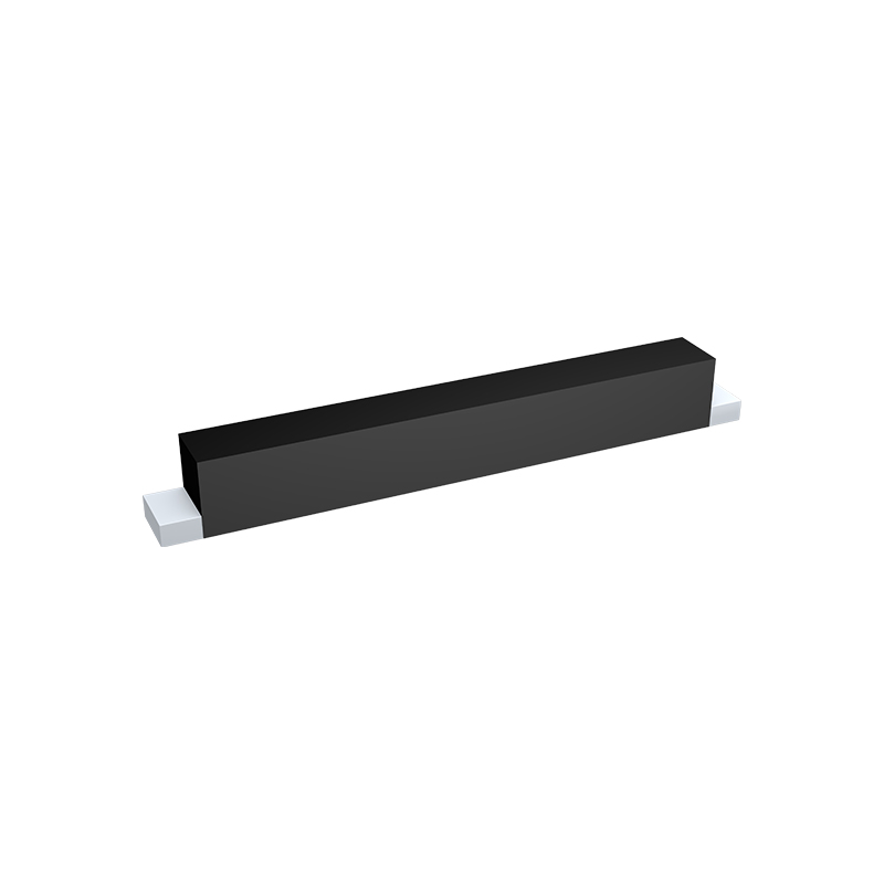
Figuring out SMD resistor markings can feel like cracking a secret code, but once you know the system, it's surprisingly logical. Most resistors use a three- or four-digit numeric code where the last digit tells you how many zeros to add. For example, "103" means 10 followed by three zeros—10,000 ohms, or 10k. A four-digit code like "1001" gives you 100 with one zero, so 1,000 ohms, or 1k. The trick is remembering that values under 100 ohms often use an "R" as a decimal point, so "4R7" is 4.7 ohms, and "R22" is 0.22 ohms. This R-notation eliminates ambiguity and makes it easy to read at a glance without counting decimal places.
Size standards add another layer of potential confusion, but they follow a straightforward metric pattern. The common sizes—0402, 0603, 0805, and 1206—are just dimensions in hundredths of an inch: 0402 is 0.04 by 0.02 inches. In metric, that's about 1.0 by 0.5 mm, but manufacturers often stick to the imperial naming convention even when giving metric equivalents. The size directly affects power handling and ease of soldering; 0402 parts are tiny and hard to hand-solder, while 1206 components are much friendlier for prototyping. There's no single "best" size, but knowing the trade-offs helps you pick without second-guessing. Once you associate the code digits with real-world dimensions, the sizes stop being abstract numbers and start making practical sense on the board.
The real key to avoiding confusion is understanding that these codes aren't arbitrary—they're designed for quick identification when you know the rules, but they can trip you up if you mix imperial and metric sizing or misread a marking under poor lighting. A magnifying glass becomes your best friend for tiny 0201 parts, where the print is microscopic and sometimes replaced by color-coded dots. EIA-96 marking, which uses a two-digit number plus a letter for 1% tolerance resistors, looks cryptic but is just a lookup table away: "01C" translates to 100 with a multiplier of 100, giving 10k ohms. Rather than memorizing every combination, keep a reference chart handy until the patterns become second nature. With a little practice, you'll be scanning a board and decoding values almost as fast as reading through-hole color bands—no stress, just a skill that builds with each project.
The Hidden Factors That Decide Your SMD Resistor’s Performance
When specifying an SMD resistor, it’s easy to fixate on resistance value and tolerance—but those numbers only tell part of the story. Subtle material properties and manufacturing nuances often steer how the part behaves under real electrical stress. For instance, the choice of resistive element (thick film, thin film, or metal foil) impacts not just initial accuracy but also long‑term drift, noise, and temperature coefficient. Thick film parts might cost less, yet their granular structure can introduce excess 1/f noise in sensitive analog front‑ends. Thin film and foil, by contrast, offer better stability but at a higher price, and their thin active layers can be surprisingly vulnerable to pulse‑induced hot spots.
Layout and termination style add another layer of invisible influence. The way current enters and flows through a surface‑mount resistor can create localized heating that derates the component far below its datasheet rating. Wide terminal designs and proper heat‑sinking into the PCB copper help, but also alter the resistor’s effective power handling in ways a simple power number can’t capture. Moreover, the plating of the terminations—tin, nickel‑barrier, or palladium‑silver—can quietly seed corrosion in humid or corrosive environments, eventually turning a stable 1% resistor into a drifting 5% liability.
Even the intrinsic magnetics of the resistor’s construction matter. Spiral‑trimmed thick film resistors, for example, form a microscopic coil that adds inductance, potentially sabotaging high‑speed switching circuits or RF designs. Meanwhile, the voltage coefficient of resistance (VCR) emerges when the resistor experiences high E‑field gradients; a parameter rarely scrutinized until it causes distortion in a precision voltage divider. None of these factors dominate the headline specs, yet collectively they define whether your SMD resistor will serve reliably for years—or quietly undermine your circuit’s performance from the first power‑on.
How to Sidestep Common Pitfalls When Selecting Chip Resistors for High-Frequency Circuits
Many designers underestimate how a chip resistor's parasitic inductance and capacitance can wreak havoc at high frequencies. One common misstep is treating all resistors as purely resistive elements. At gigahertz levels, the package style, termination geometry, and even the orientation on the board can introduce significant impedance shifts. To avoid this, start by choosing thin-film resistors with minimal stray reactance and consider flip-chip mounting if your layout allows. Also, keep an eye on the resistive material's skin effect, which can alter the effective resistance as frequency climbs.
Another trap is fixating solely on the resistor's nominal value and tolerance while ignoring its high-frequency noise characteristics. Excess noise—both thermal and current-induced—can degrade signal-to-noise ratios in sensitive RF chains. Prioritize components with low noise indices, and be wary of thick-film types in low-signal-level stages. Datasheets rarely tell the whole story here, so prototyping with candidate parts and measuring noise under actual operating conditions is a prudent step that many skip in fast-paced development cycles.
Finally, thermal management is often an afterthought until a circuit mysteriously drifts out of spec. At high frequencies, the power dissipated in a chip resistor may be small, but localized heating can still change its impedance and cause unforeseen detuning. Ensure your PCB layout provides adequate heat sinking, especially for parts in high-density RF assemblies. Sometimes, splitting the resistance into two parallel units not only spreads heat but also reduces the parasitic inductance, solving two problems at once. Testing across temperature extremes early in the design process saves costly re-spins later.
Beyond the Datasheet: Real-World Trade-offs in SMD Resistor Applications
When an engineer first reaches for an SMD resistor, the datasheet is the natural starting point – a neatly tabulated world of resistance values, tolerances, and power ratings. But the moment that tiny component is soldered onto a real PCB, a host of second-order effects come into play. Thermal management becomes a subtle dance: a resistor rated for 0.25 W at 70 °C might need significant derating if it's tucked between a hot voltage regulator and a cramped enclosure with poor airflow. Proximity to other heat sources can push junction temperatures beyond safe limits, turning a straightforward spec into a failure waiting to happen. Beyond heat, the physical construction introduces parasitic inductance and capacitance that transform a 10 kΩ resistor into a complex impedance at high frequencies, something no static datasheet value can fully capture.
Noise performance is another realm where datasheet figures can be misleading. While a thick-film resistor might boast a tight tolerance, its excess noise – caused by the granular structure of the resistive element – can wreak havoc in sensitive analog front-ends. Metal foil or thin-film alternatives, often chosen for their low noise, bring their own quirks: higher cost, delicate construction, and sometimes poorer pulse-handling capability. The trade-off extends to voltage coefficients as well; a resistor that appears linear on paper may subtly distort a high-voltage signal, introducing errors that only surface in final testing. Even mundane choices like package size carry hidden consequences. A smaller 0402 footprint saves space but concentrates heat and demands precise assembly, while a larger 1206 part offers better power dissipation at the expense of board real estate and increased parasitic inductance.
Ultimately, navigating these real-world compromises requires a mindset that blends physics with practical experience. It's about recognizing that a resistor is never just a resistor – it's a thermistor, a tiny inductor, a capacitor, and a noise source all rolled into one. Successful designs emerge from accounting for the environment, the signal characteristics, and the subtle interactions that happen when thousands of these components work together on a dense board. By looking past the datasheet's optimistic single-point specifications and considering the entire operational envelope, engineers can make informed choices that balance cost, performance, and reliability.
Future-Proofing Designs: The Shift Toward Miniaturized and High-Power SMD Resistors
The relentless push for smaller, faster, and more efficient electronics has redefined the role of the humble resistor. Gone are the days when a standard 0603 or 0805 chip could handle most power needs without a second thought. Today's densely packed PCBs demand components that shed heat quickly and stay electrically stable under duress. This is where miniaturized, high-power SMD resistors earn their keep—by squeezing superior power handling into footprints that defy old limits.
Material science and clever thermal design sit at the heart of this evolution. Rather than simply shrinking a part and accepting a drop in performance, manufacturers now use advanced substrates like aluminum nitride, thick-film cermet layers, and optimized termination styles to channel heat away from the resistance element. The result is a 0402 or even 0201 resistor that can dissipate several times the power of its conventional counterpart, making it a crucial ally in automotive under-hood modules, portable medical gear, and 5G infrastructure.
Choosing such resistors isn't just about staying current—it's about building headroom into a design from day one. As processor speeds climb and functional density increases, designers are leveraging these parts to simplify layouts, reduce component count, and eliminate mid-board hotspots. By moving to high-power SMD resistors early, you avoid painful mid-cycle re-spins and ensure your product remains resilient well into the next wave of performance demands.
FAQ
An SMD chip resistor is a tiny rectangular component designed for surface mount technology, soldered directly onto the surface of a printed circuit board without leads passing through holes. Unlike through-hole resistors, SMD types are much smaller, offer better high-frequency performance, and allow automated assembly, making them ideal for modern miniaturized electronics.
These standardized sizes were originally based on imperial measurements (e.g., 0805 means 0.08 inches by 0.05 inches) and have become an industry norm to ensure compatibility across different manufacturers. They help designers choose the right footprint for their PCB layout, balancing power handling, solderability, and board real estate.
The markings are a compact code for the resistance value. For three digits, the first two are significant figures and the third is the multiplier (number of zeros). So '472' means 47 followed by two zeros, or 4.7k ohms. A four-digit code works similarly, with three significant figures and a multiplier.
The power rating depends on the resistor's size and ambient temperature. Larger packages like 1206 can dissipate more heat than an 0201. You should calculate the expected current and voltage drop across the resistor, then pick a rating with some headroom, typically double the expected dissipation, and consider derating if operating at high temperatures.
Most SMD chip resistors use a thick film ruthenium oxide paste printed onto a ceramic substrate because it’s cost-effective and stable. For higher precision or lower temperature coefficient, thin film nichrome tantalum nitride is used. Metal foil offers the best stability and lowest noise but at a higher cost.
Yes, but you need to account for parasitic inductance and capacitance. Small packages like 0201 or thin film resistors have less parasitic effects, making them suitable for GHz-range circuits. Always check the resistor's frequency response or use a dedicated high-frequency resistor model if precision is critical.
TCR indicates how much the resistance changes with temperature, expressed in ppm/°C. In precision analog circuits, a low TCR (e.g., ±25 ppm/°C or less) is crucial to maintain accuracy over varying temperatures. Thick film resistors usually have higher TCR, while thin film and metal foil offer much lower values.
Conclusion
China’s dominance in SMD resistor manufacturing goes far beyond low labor costs—it’s rooted in a dense, vertically integrated supply chain where ceramic substrates, resistive pastes, and laser trimming equipment are all sourced within hours, not weeks. This proximity slashes lead times and enables the rapid iteration that global electronics brands depend on. Yet navigating the product landscape still trips up many engineers because of confusing coding systems and footprint standards. Once you decode the three- or four-digit markings and match them to real-world sizes like 0603 or 0805, selection becomes straightforward. More importantly, resistor performance is shaped by factors that datasheets often downplay: the temperature coefficient of resistance might look fine on paper, but combined with board flex, humidity, and self-heating, it can drift beyond acceptable limits. Even the choice between thick-film and thin-film construction subtly shifts noise, stability, and pulse handling in ways that only become visible after prototyping.
High-frequency circuit designers often treat chip resistors as ideal components, forgetting that their helical trimming patterns and end-cap connections introduce parasitic inductance and capacitance that warp impedance above a few hundred megahertz. Avoiding this pitfall means scrutinizing the fine print of RF performance or simply using dedicated microwave resistors. Beyond the datasheet, every application forces trade-offs: a resistor that survives 10 kV surges might need a body size that wrecks your board real estate, while ultra-precision metal foil types can inflate BOM cost needlessly. These real-world compromises demand a mindset shift from “what’s specified” to “what actually works.” Looking ahead, the industry’s appetite for miniaturization—think 01005 and beyond—collides with the need for higher power ratings, pushing manufacturers to experiment with exotic materials like metal strip technologies and integrated thermal vias. For design engineers, future-proofing means anticipating these trends now, ensuring that today’s schematic can gracefully accommodate tomorrow’s tougher, smaller resistors.
Contact Us
Contact Person: Yuying Gao
Email: [email protected]
Tel/WhatsApp: +86 18926013721
Website: https://en.milliohm.net/