

Custom Ultrasonic Spray Coater: Precision Coating Solutions for Advanced Manufacturing
2026-08-24
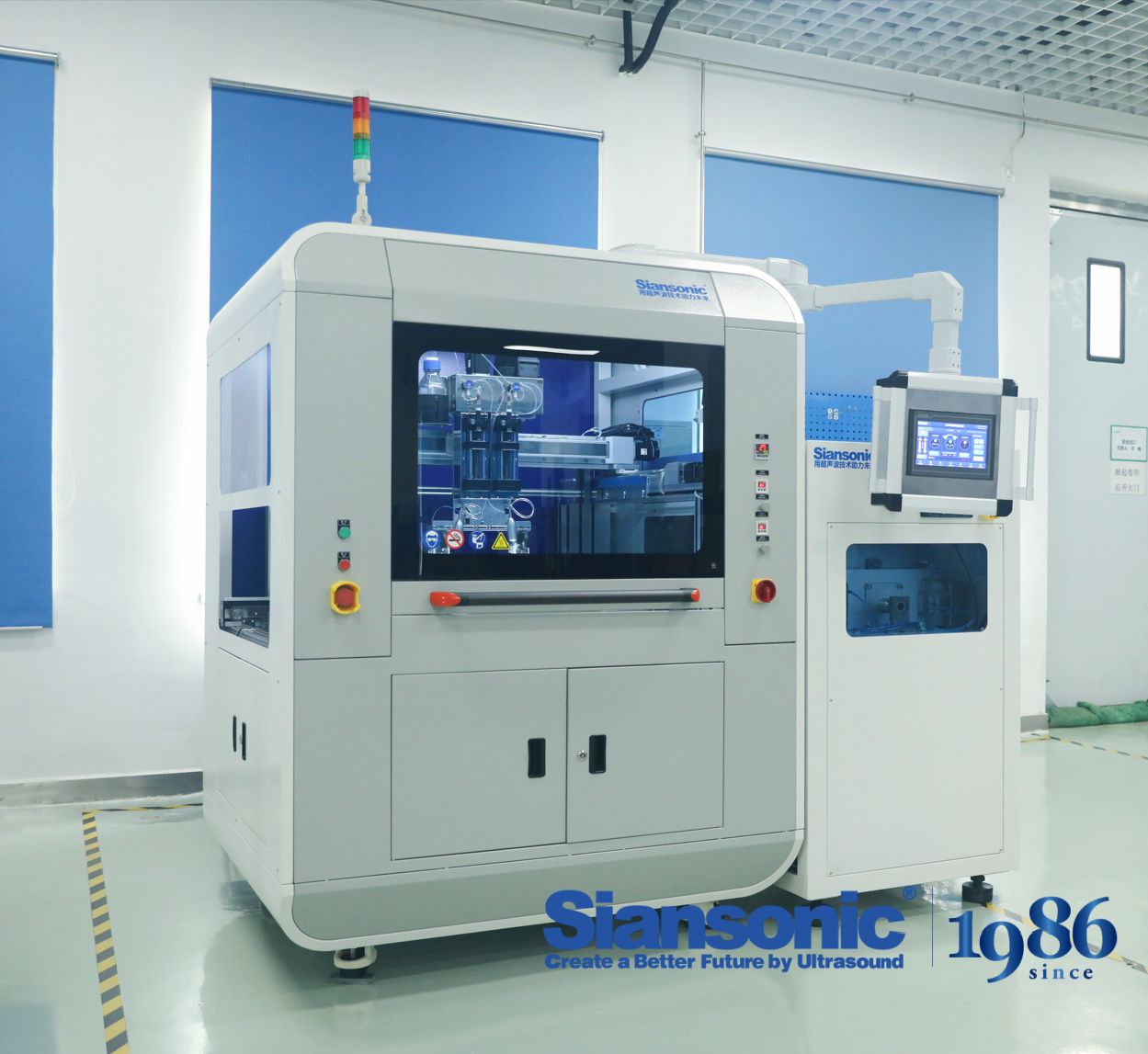
In the high-stakes world of advanced manufacturing, coating uniformity can make or break product performance—yet traditional spray methods often fall short on complex geometries. What if you could achieve micron-level precision without compromising speed or flexibility? Discover how Siansonic's custom ultrasonic spray coater, engineered by Siansonic, redefines precision coating for the most demanding applications. From fuel cells to medical devices, this technology turns impossible coating challenges into repeatable, high-yield processes.
Ultrasonic Atomization Without the Clogging Headaches of Air Jets
Traditional air-jet atomizers rely on high-velocity gas streams to shear liquid into droplets, but this approach comes with a well-known weakness: clogging. Orifices narrow enough to produce fine mists are equally narrow enough to trap particulates, dried residues, or even slight viscosity shifts, leading to downtime and frequent cleaning. Ultrasonic atomization sidesteps this entirely by using high-frequency vibrations on a solid surface—typically a piezoelectric transducer—to break liquid into droplets without any small-bore nozzle in the liquid path. The liquid simply feeds onto a vibrating mesh or horn, where capillary waves and cavitation do the work. There is no tiny opening to obstruct, no air pressure to balance, and no delicate tip to wear down from repeated blockages.
The practical advantage shows up in applications where liquids are not perfectly clean or where formulation changes are common. Coatings, medical aerosols, humidification, and even fuel delivery all benefit from a system that tolerates higher solids content, suspended particles, or shear-sensitive compounds. Since the atomization surface is typically flush or slightly recessed, buildup can be wiped away without disassembly, and the lack of a narrow passage means the device keeps running long after a conventional air jet would have required maintenance. For operators, this translates into fewer interruptions, less solvent flushing, and a more predictable droplet size distribution—because the vibration frequency, not a fragile orifice geometry, defines the mist quality.
Ultrasonic systems also remove the need for compressed air infrastructure, which brings secondary benefits beyond clog resistance. Without air jets, there is no risk of oil contamination from compressors, no loud gas expansion noise, and far less overspray caused by turbulent airflow. The liquid is delivered gently and precisely, often at lower velocities, which improves transfer efficiency and reduces waste. While ultrasonic atomization may not suit every high-throughput industrial scenario, its clog-free operation and quiet, low-energy profile make it an increasingly attractive replacement wherever reliability and cleanliness outweigh raw spray force.
Coating Conformal Surfaces with Minimal Overspray and Shadowing
The core difficulty with conformal coating on complex geometries isn't just reaching every surface, but doing so without piling up material in recesses or leaving dry spots behind tall components. Overspray usually comes from broad fan patterns that throw droplets past the edges, while shadowing occurs when a perpendicular feature blocks the spray path. A practical fix starts with mapping the part's silhouette and adjusting the nozzle distance and angle so the plume wraps around corners instead of bouncing off them.
Reducing air pressure and moving to a narrower, more controlled fan helps keep the wet film where it belongs. Some lines add electrostatic attraction to pull charged droplets onto grounded substrates, which cuts bounce-back and lets the coating creep into low-visibility areas. Rotating the workpiece during spray passes also evens out coverage, especially around connectors, pins, and standoffs that would otherwise create hard shadows.
Masking still matters, but it can be minimized by programming the robot to start and stop the spray outside critical zones rather than relying on bulky tape. For high-mix production, a combination of selective coating valves and short, overlapping strokes tends to yield cleaner edges and a more consistent thickness than trying to cover the whole board in one pass. The goal is a film that follows the surface contour with no thick rims, no thin patches, and almost no mist escaping into the surrounding air.
Fine-Tuning Droplet Size for Conductive Inks and Battery Slurries
Getting the droplet size right in conductive inks and battery slurries isn't just a matter of turning a dial—it's a balancing act between fluid rheology, nozzle geometry, and the specific deposition method at hand. For inkjet systems, sub-20-micron droplets with tight size distribution prevent satellite formation and keep line resolution crisp, while aerosol jetting tolerates a wider range but still demands consistent evaporation behavior mid-flight. Battery slurries, on the other hand, often rely on coarser droplets during spray drying or slot-die coating, where uniformity matters more than fineness to avoid agglomerates in the dried electrode layer.
One underappreciated lever is the interplay between surface tension and viscosity under shear. As conductive inks shear through a nozzle, polymer chains align and temporarily lower viscosity, which can cause droplet breakup to shift unpredictably if the relaxation time is too long. Adding a small amount of high-boiling co-solvent or tuning the particle-to-binder ratio often stabilizes the droplet formation window. For slurries with high solids loading, pulsed flow or ultrasonic atomization can break up the stream without introducing air bubbles that later create pinholes in printed traces or coated films.
In practice, operators iterate between laser diffraction measurements and high-speed camera imaging to capture both the mean droplet diameter and the tail of the distribution. A slurry that looks fine under a microscope may still produce overspray or uneven wet film thickness if a few large droplets skew the Sauter mean diameter. By mapping droplet size against print speed, standoff distance, and drying temperature, it becomes possible to lock in a window where edge sharpness, electrical conductivity, and adhesion all stay within spec—without resorting to trial-and-error runs on expensive pilot lines.
Scaling from Benchtop Prototypes to High-Mix Production Runs
Moving from a benchtop prototype to a production line that handles dozens of product variants is rarely a linear scale-up. Prototypes are built to prove a concept, so they tolerate hand-fitted parts, improvised wiring, and process steps that work only because one engineer knows the exact sequence. In high-mix production, those informal workarounds become bottlenecks. The first step is to audit the prototype build and identify every operation that depends on tacit knowledge or non-repeatable manual adjustment. Those areas need dedicated fixtures, torque specs, or visual guides before you even think about line balancing. Otherwise, the same design that worked beautifully on the bench will generate scrap and rework the moment operators rotate across shifts.
One underappreciated aspect of high-mix scaling is changeover economics. A line that produces twenty variants a week spends more time switching than assembling. Instead of speeding up the assembly itself, look at how tooling is located, how feeders are replenished, and how work instructions are delivered. Quick-release mounts, color-coded part bins, and digital work instructions that update automatically per variant can cut changeover time without costly automation. It also helps to group product families by shared geometry or common components, so the line switches between similar builds rather than jumping from a small enclosure to a large chassis and back. That grouping is not always obvious from engineering drawings, so involve the operators who actually run the line when deciding the production sequence.
Finally, treat the first few production runs as a data collection exercise, not just a delivery milestone. Capture cycle times per station, defect types, and material consumption for each variant. Compare those numbers against the prototype build records. You will often find that a joint that was easy to solder by hand becomes a cold-solder risk when done by a new operator under time pressure, or that a 3D-printed alignment jig from the lab wears out after three hundred cycles. Feeding these observations back into the design and process documentation—before the next high-mix order arrives—is what turns a fragile prototype success into a repeatable production capability.
Closed-Loop Flow Control That Stabilizes Wet Film Thickness
Traditional closed-loop controllers chase a set point by reacting to error after it appears. In slot-die coating, that lag lets film thickness drift beyond tolerance before correction begins. A better loop stabilizes the wet film by predicting thickness from upstream variables—pump speed, die pressure, substrate velocity—and adjusting before deviation becomes visible downstream. The control law is not simply proportional-integral; it blends a physics-based forward model with a slow trim on the measured thickness. This keeps the wet film inside a narrow band even during acceleration ramps and coating start-up, where open-loop methods typically lose several meters of substrate.
The key is treating wet film thickness as a dynamic state, not a static output. Since the wet layer cannot be measured instantly at the coating bead, the controller relies on a mass balance: flow rate in minus substrate take-up rate, integrated over the bead length. A modified Smith predictor handles the transport delay from bead to downstream gauge, letting the loop act on current conditions rather than stale feedback. Operators see fewer manual interventions and less edge bead variation, because the loop compensates for viscosity shifts and die lip temperature drift before they surface as thickness error.
When tuned correctly, the stabilized loop reduces thickness variance by half compared to feedback-only control, especially during splice events or line speed changes. The wet film remains uniform enough that downstream drying and curing operate in a predictable window, cutting solvent usage and improving coating yield. This approach favours a lower gain on the slow trim and a higher gain on the fast forward path—inverting the usual practice of aggressive feedback that can amplify noise and cause oscillation in thin films.
Cutting Material Loss on Expensive Catalyst and Nanoparticle Coatings
The economics of industrial catalysis rarely survive careless handling. Platinum, palladium, and rhodium prices swing wildly, yet labs still lose milligrams of these metals to sloppy dip-coating, uneven spray patterns, or transfer steps that scrape off more than they deposit. The real problem isn't the material cost alone—it's that every lost gram forces a redesign of the coating schedule, disrupts batch consistency, and pushes nanoparticle-loaded slurries into waste streams that cost extra to treat. Smart teams now measure loss at each stage with a microbalance before and after coating, then tune viscosity, withdrawal speed, and drying angle to keep the slurry where it belongs.
One often-overlooked leak is the edge effect on flat substrates. When a doctor blade levels a catalyst ink, the meniscus at the borders pulls extra liquid sideways, leaving a thicker rim that later flakes off during calcination. Masking the edges with a sacrificial tape or switching to a slot-die coater can recover 5–8% of the precious metal that would otherwise end up as dust on the oven floor. Another quiet thief is the cleaning cycle: flushing lines and nozzles with solvent after each run seems cheap, but if the rinse isn't collected and distilled for reuse, a week of production can silently pour several hundred dollars of catalyst down the drain.
Nanoparticle coatings add their own twist. Because particles settle and agglomerate, operators often over-dilute the suspension to extend pot life, only to realize the final film is thinner than spec and requires a second pass—doubling the opportunity for loss. A better approach is to monitor the zeta potential and particle size inline, adjusting pH or surfactant concentration just enough to keep the dispersion stable without adding excess liquid. Pair that with a reclaim system that filters overspray from the booth air and returns the solids to the mixing tank, and a coating line can push material utilization above 95%. The difference shows up not just in the ledger but in the consistency of every reactor batch downstream.
FAQ
It works well with thin, uniform films—think photoresists, conductive inks, nanocoatings, biomaterials, and even sensitive polymer solutions. Because the nozzle vibrates at high frequency, it doesn’t clog the way conventional spray systems often do.
The nozzle breaks liquid into fine droplets using high-frequency vibration rather than air pressure. This creates a softer mist, tighter droplet distribution, and a more even layer with far less overspray.
Yes, the whole point of a custom unit is to adapt to your substrate size, motion control needs, liquid delivery, and even cleanroom constraints. You’re not locked into a one-size-fits-all setup.
Both. Smaller configurations fit benchtop development, while the same core nozzle technology scales to inline or multi-axis robotic coating for production volumes.
Because it's a low-velocity spray, there’s minimal impact on delicate surfaces. You can also heat the substrate only as much as the process requires, avoiding thermal damage.
Ultrasonic coating typically reaches transfer efficiency well above 90%. That means less overspray, lower chemical usage, and simpler exhaust requirements.
With the right motion platform and nozzle orientation, yes. It’s often used on curved lenses, medical device components, and textured surfaces where dip or roll coating would struggle.
Conclusion
Custom ultrasonic spray coaters remove one of the oldest pain points in precision coating by replacing air-jet nozzles with a vibrating tip that atomizes liquid without narrow orifices prone to clogging. That design change pays off immediately on complex or three-dimensional parts, where a low-velocity mist wraps around edges and into recesses with far less overspray and shadowing than a pressure-driven spray. Because the ultrasonic frequency and liquid flow can be tuned independently, droplet size becomes a controllable variable rather than a fixed limitation—especially useful for conductive inks and battery slurries whose viscosity shifts between batches. Instead of checking wet film thickness after the fact and scrapping off-spec panels, the system links pump output to real-time flow feedback, holding deposition steady across the full substrate.
The same platform moves from benchtop prototypes to high-mix production runs without a tooling overhaul, since nozzle height, scan speed, and fluid delivery stay recipe-driven and repeatable. For costly catalyst inks or nanoparticle suspensions, that control translates into direct material savings: a tighter plume and closed-loop flow regulation cut overspray enough to reduce consumption by double digits in many lines. Rather than flooding a surface to guarantee coverage, operators dial in a narrow deposition window and let the coater maintain it run after run. The result behaves less like a traditional spray booth and more like a metered printing step, which is exactly what advanced manufacturing demands when every micron of wet film and every gram of active material affect yield, performance, and final cost.
Contact Us
Contact Person: Ivy Zhang
Email: [email protected]
Tel/WhatsApp: +86 1081502288
Website: https://www.siansonic.com/